ON-LINE MANUAL
Installation and operation of the vibrator
Mounting
Before
mounting the vibrator make sure the location has been carefully selected
to insure the best working results (refer to Chapter 3).
The
mounting area must be clean and even. Please note that an uneven mounting
area may cause the vibrator to malfunction due to torsion in the vibrator's
body.
The
vibrator should be placed, whenever possible, so that the rotation
of the ball, roller or turbine supports the direction of material
flow.
It
is easy to verify the correct placement with the help of the air inlet
as shown in figure 6.1.
Support
of flow and correct placement on a bin
Check
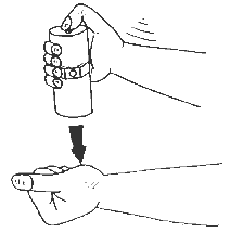
free movement of the piston
Before
mounting the Piston Vibrator FP-series, check to make sure that the
piston is moving freely. Hit the vibrator against the ball of the
thumb. You will hear a metallic "clack" of the piston when
knocking the end cap. If the piston is not moving freely, add some
drops of petroleum (kerosene) into the air inlet. It will loosen the
clog of the piston which is probably caused by the congealed oil we
use in manufacturing.
Screws and nuts
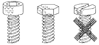
Allen
Screws / Hexagon Screw / Slotted Screw
The
following screw sizes have to be used:
| Model |
8/10 |
13/16 |
20/25 |
30/36 |
40/48 |
60/70 |
| K-series |
M6 |
M8 |
M8 |
M10 |
---- |
---- |
| GT-series |
M6 |
M8 |
M8 |
M10 |
M16 |
M16 |
| Model |
50 |
65 |
80 |
100 |
120 |
. |
| R-series |
M6 |
M8 |
M8 |
M10 |
M16 |
. |
| T-series |
M6 |
M8 |
M10 |
M12 |
---- |
. |
| Model |
2 |
3 |
4 |
5 |
6 |
7 |
| DAR-series |
M6 |
M8 |
M10 |
M12 |
M16 |
M16 |
| Model |
12 |
18 |
25 |
35 |
. |
| FP-series |
M8 |
M10 |
M12 |
M12 |
. |
Allen
Screws or Hexagon Screws with a minimum quality of 8.8 are recommended.
Similarly, the nuts should conform to 8.8 quality.
Slotted
Screws or other types of screws with less tensile strength should
be avoided.
The
screws should be long enough so that at least one full thread is out
of the nut.
If
a threaded hole in the object is used for mounting, the screw should
be torn in at least 1.5 times the screw diameter.
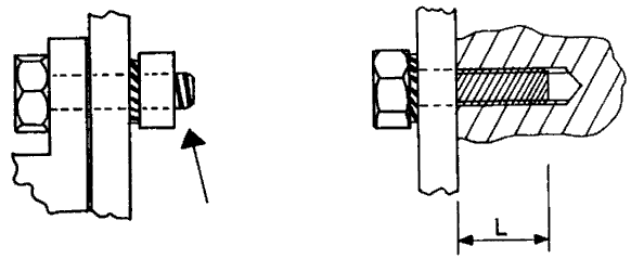
Lengths
of the screw in the thread
For
FP-series the length of the screw in the vibrator thread should be
as follows:
| FP-Type |
12 |
18 |
25 |
35 |
| Minimum
(mm) |
10 |
10 |
12 |
12 |
| Maximum
(mm) |
13 |
13 |
15 |
15 |
CAUTION: Always
use a Tooth Lock Washer or a Spring Lock Washer.
The use of an adhesive sealant (LOCTITE 270 for instance) is suggested.
Please follow the manufacturer's instructions.
Never
use an ordinary Flat Washer or a Curved Washer because these washers
do not stop movement, and loosening of the screw during vibration
may occur.

Tooth
Lock Washer / Spring Lock Washer / Curved Washer
The
washer should be placed between mounting plate and nut, and between
mounting plate and screw for FP-vibrators.
The
tightening torque must not exceed the following values :
| Thread |
Minimum |
Maximum |
| M6 |
6 N |
10 N |
| M8 |
15 N |
21 N |
| M10 |
30 N |
42 N |
| M12 |
50 N |
72 N |
| M16 |
150 N |
174 N |
Minimum / maximum torque
NOTE: FP-series : The socket with the mounting thread is the end cap with
the smaller diameter. The thread in the other end cap (air exhaust
port) is not metric!
The
vibrator is to be placed, whenever possible, so that the rotation
of the ball, roller or turbine supports the direction of material
flow.
It
is easy to verify the correct placement with the help of the air inlet
as shown in figure 6.8.
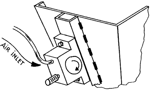
Support
of flow and correct placement on a bin
CAUTION: Make sure the vibrator is securely fixed! We strongly recommend
that you retighten the screws after a few minutes of operation. A
loose vibrator may fall down and harm people or machinery.
Air connection
The
air pressure tube should be wide enough to allow a good air flow.
The main air line should be dimensioned according to paragraph 2.4..
The connection from the main line to the vibrator is made with a short
flexible tube. Make sure the inner span of this flexible connecting
tube conforms to figure 6.9.
| Profile
Type |
50 |
65 |
80 |
100 |
120 |
180 |
| Inner
Span (mm) |
8 |
8 |
12 |
16 |
16 |
20 |
Fig.
6.9. : Minimum requirements of inner span of connecting tube
Make
sure the air pressure tube at the air inlet port is flexible and freely
movable so that vibration does not harm the tube at the transition
piece. The tube is to be securely fixed at the object side, so that
the tube may not come in resonance. You can let the tube hang from
a structure point directly to the inlet port, but make sure that it
does not create a safety hazard.
Make
sure that the tube can never be buckled.
NOTE: The pipe thread is BSP type (British Standard Pipe) but will accept
US NPT (National Pipe Thread) that is conical and has one extra turn
per inch. Tighten very closely using Teflon-tape
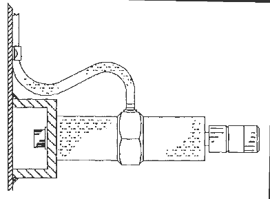
Fixation
of the air pressure tube
The
filter, regulator and lubricator unit should be placed as close as
possible to the vibrator (less than 2 m).
If
an electromagnetic valve is connected into the air line for intermittent
operation of the vibrator, the distance between vibrator and valve
should be less than 50 cm. This will guarantee a proper and immediate
start and stop.
Only
one lubricator unit needs to be used for a maximum of three vibrators.
The lines from the junction to every vibrator should be of the same
length to ensure that all vibrators are supplied with same pressure
and flow through.
Again,
when using electromagnetic valves, place each one within 50 cm of
every vibrator so it is guaranteed that all vibrators will start and
stop at the same time.
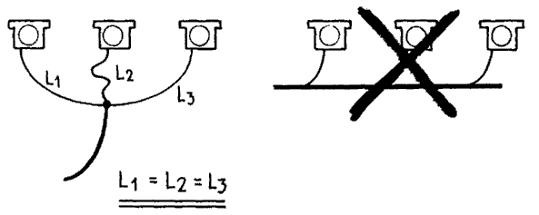
Connection
of three vibrators to one lubricator unit
If
a lubricator is used, the oil must be ISO VG5 as explained in paragraph
2.2.
Please
note that suppliers of servicing units (filter-regulator-lubricator)
sell their own oil for lubrication. Please verify it conforms to ISO
VG5!
We
recommend that you add a few drops of kerosene into the vibrator's
air inlet before mounting the air tube. Kerosene will dispel the corrosion
protective additive inside new vibrators during the first few seconds
of operation.
Air Muffler
All
vibrators except the R-series may be equipped with silencers or an
exhaust hose. The use of the following silencers is recommended.
| Vibrator
Types/Models |
Silencer |
Size |
Order-No. |
| GT-8
/-10, R-50, FP-12 / -18 |
Filter
Type |
1/8" |
44025 |
| K-8
to 25, GT-13 to 25, T-50 to 65, R-65 / -80 |
Filter
Type |
1/4" |
44026 |
| K-30
/ -36, GT-30 to 48, T-80 to 100, R-100 / -120 |
Filter
Type |
3/8" |
44027 |
| DAR-2 |
Sintered |
1/8" |
39371 |
| DAR-3
/ -4 |
Sintered |
1/4" |
39372 |
| DAR-5
/ -6 / -7 |
Sintered |
3/8" |
39373 |
| FP-25
/ 35 |
Free Flow |
1/4" |
44029 |
Fig.
6.12. : Silencer cross reference
Silencers
may clog due to dirt in air; hence, the use of air line filters is
strongly recommended, but clogged silencers (filter types and sintered
types) may be washed out with petroleum (kerosene). FF-types (Free-Flow
1/4" ) can be unscrewed, and both parts can be blown through
with air pressure.
Instead
of using silencers the exhaust air may be blown through a hose. Make
sure that the hose inner span is about double the size of the air
pressure tube, otherwise the full pressure (difference from air inlet
port to the end of the exhaust hose) is not transformed into mechanical
energy. As mentioned in Chapter 2.4. pressure loss in pipes (whether
supplying nor exhausting) must not exceed 0.5 bar in total.

Pressure
Loss
The
exhaust pipe should not exceed 2 m.
Outdoor application
All
FINDEVA vibrators may be used outdoors when operated under the following
conditions :
The
vibrator is to be installed so that no fluid may reach it. If the
vibrator is exposed to fluids (rain drops or other moisture), one
of the following steps must be taken:
-
The
vibrator should be mounted so that the exhaust port with silencer
is turned against the ground or the exhaust port should be connected
to a hose that is mounted so its end is against the ground, not
allowing liquid or dirt to enter.
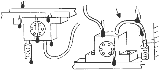
Mounting
outdoors or exposed to liquids, dirt, etc.
CAUTION: Never operate vibrators without a silencer or exhaust hose if
dirt, liquids or other particles (concrete powder, caustic solution,
etc.) can enter the exhaust port.
Operation
After
having successfully installed the vibrator, it can be set into operation.
WARNINGS:
- Wear
ear protection around pneumatic vibrators!
- Operation
without a silencer should be avoided to keep the noise level (and
possibility of ear damage) reduced as much as possible!
- Make
sure the lubricator (if any) is filled.
- Make
sure that the maximum air pressure to the vibrator is 115 psi!
- Check
again that mounting screws are tightly fastened.
- Make
sure the air pressure tube is connected to the inlet port.
- Vibrators
mounted on bins and hoppers should not be operated if bin or hopper
is empty since this may cause structural damage.
When
starting the first time, the vibrator might reach its nominal frequency
and force after only a few minutes. This is because the moving parts
are covered with grease and the temperature is low so that the grease
is stiff. All vibrators are run during the final inspection in the
plant for some minutes but because of stocking the grease may have
a chance to clog again.
We
recommend that you operate vibrators intermittently for several reasons:
- the lifetime
of the vibrator is extended
- costly air
pressure energy is conserved
- operate
only when material flow is required and shutters and gates are
open to prevent material from packing in the bin, hopper or chute.
- an Operating
Factor of 10 to 30 seconds ON and 1 to 5 minutes OFF has been
found to be most efficient for most applications.
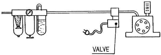
Intermittent
operation
For
intermittent operation, we recommend the use of electromechanical
valves driven by timers or the machinery control system. The valve
has to be set in line between the lubricator and the vibrator. The
closer the valve is set to the vibrator the stronger start- and stop-intervals
are. When the valve is set farther from the vibrator, the air pressure
volume remaining in the air pressure tube has to be emptied and refilled.
Very
often there is no need to run the vibrator at full power. Air power
energy can be saved using a pressure regulator. Adjusting to the resonant
frequency of the system extends the life time as well.
The
frequency of all vibrators can be controlled with the help of pressure
regulators in the supply pressure line. The FF-silencer connected
to the piston vibrator's exhaust also allows adjustment of the vibration
amplitude.
WARNING: For the following inspection wear ear protection !
When
operating a vibrator for the first time, disconnect the exhaust hose
and run the vibrator and measure its frequency and force. Do the same
again with the exhaust hose mounted. Any difference in the values
obtained show pressure and energy loss in the exhaust hose. If this
occurs, increase diameter of the hose or cut the length of the hose.
The
same procedure can be done with a silencer to verify the air flow
is sufficient or to detect clogging.
If
the vibrator cannot be set into operation or the desired operation
power cannot be obtained please refer to Chapter 7.2.1. Fault Detection.

